


At the beginning of the project, mounting system installation is quite important.By reading this article, you will learn the key important steps and points in installing a PV system that will hopefully help you in your future project installations.
The components of the Solar system
1. Solar panels
2. Solar Mounting system
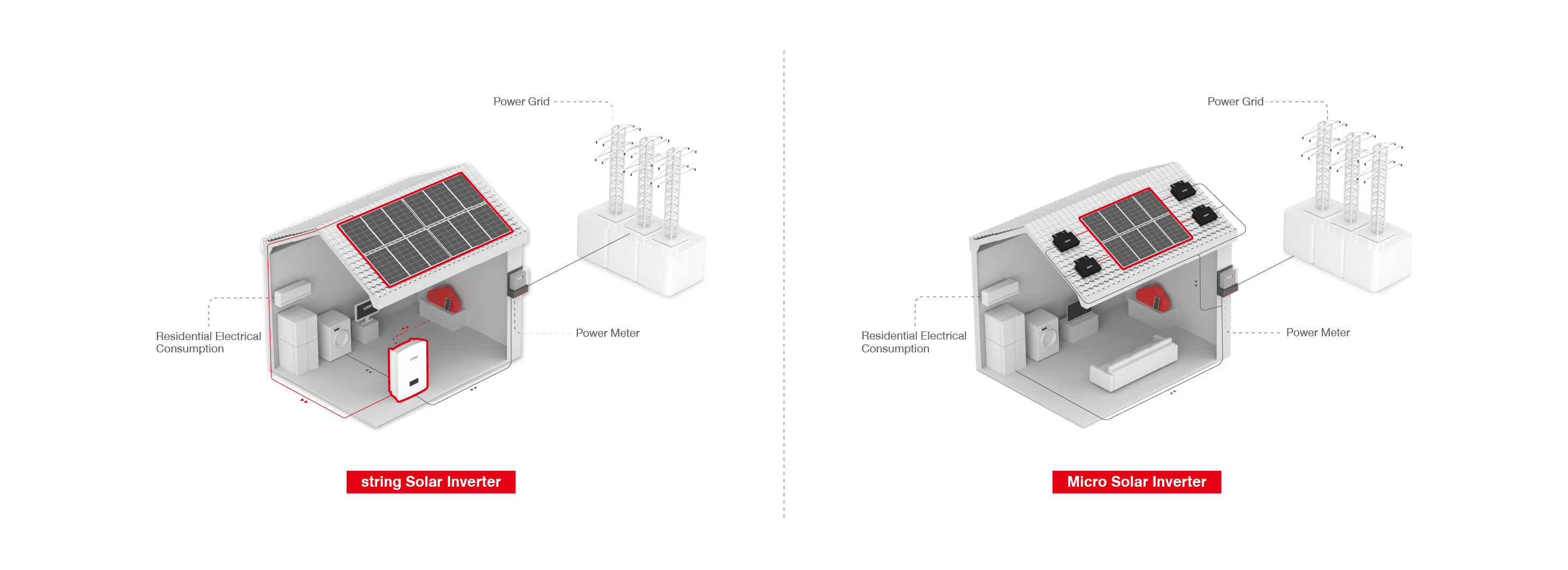
3. Inverters
4. Combiner box
Bracket installation
1. The deviation of verticality of stent is not more than ±1mm per meter, and the deviation of angle of stent is not more than ±1 degree. Bracket installation as a whole to ensure that the neat, rear column to maintain vertical and installation surface, the main keel to maintain parallel to the installation surface.
Component mechanical mounting holes should be guaranteed to fall near the two main keels, so when installing the bracket, make sure that the spacing between the two main keels of the bracket is 867-1067mm.
2. Photovoltaic bracket is grounded by 40*4 mm galvanized flat iron.
Eight steps to install a bracket on a concrete surface or flat roof
1. Clean the roof, install the foundation, and measure the installation position of the foundation using a tape measure in the roof.
2. Drill holes in the cement foundation, measuring the depth of the holes based on the foundation's thickness and the bolts' length to ascertain the bolts' M10 diameter. (The base before pre-installed bolts to address the contaminants on the threads).
3. To make sure the holes are clean, use the suction pump to vacuum the dirt out of the holes or blow them out.
4. Insert the expansion bolts into the holes and carefully tap them into place, leaving a space of 30 mm between each bolt, using wooden hammers or non-metallic hammers like leather hammers. Hammers that are not made of metal, like leather hammers, can be used to gently tap the bolt into a hole that is 30 mm apart.
5. Installation of the bottom beam or base, with the holes matching up with the bolts and the nut tightened using a wrench (in line with the method of fixing the other foundation base mentioned before).
6. Bolts will be used to secure the base and rear column in accordance with the angle at which the bracket is to be mounted.
7. When fastening the diagonal beams, utilize an angle connection to secure the rear column. The diagonal beams are fastened to the base using bolts.
8. Bolt the base and the diagonal beam in place.
9. As soon as the keel is fixed, it is important to measure the distance between the diagonal beam and the component's two ends from the edge and to keep the space between the keel and the mounting holes at ±100mm.200–300 mm, secure the keel to the diagonal with profile nuts.
10. Installing a component involves measuring its height before installation; the component's lower glass surface is 300 mm above the ground. To secure the component, use a side pressure block; first secure the lower pressure block to keep the component from slipping; the component's border is 20–30 mm from the keel's ends. To determine the component's overall parallelism, two individuals must work together during the fixing process and when using the leveling ruler or pulling the line method.
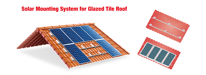
Installation of Tile Roofs
1. Measure the roof's installation position for the ceramic tile base in accordance with the dimensions indicated in the drawings, remove any pre-installed tiles, and use wood screws to secure the base to the roof purlin (try to fix all of the bases at once; if conditions prevent it, fix the two rows of keel to help with installation);
2. Installing the keel, adjusting the keel spacing based on where the component mounting holes are located to choose the keel and the mounting holes fixed in ± 100mm; using profiled nuts via the beam placed in the ceramic tile base to modify the border's position using hexagonal bolts tightened;
3. Component installation: The first component will be positioned on the guide rail's side. Using a ruler, ascertain that the component border's overall parallelism measures at least 20 mm from the guide rail's side. Next, use the pressure block's side to secure the installation of the second component. Finally, use the pressure block to tighten the pressure block using the diagonal fixation method. The remaining components will be installed elsewhere. The installation of the remaining parts is done in order.
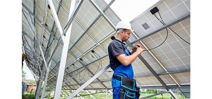
Installing Modules
1. The module and the mounting surface should be separated by a space greater than 50 mm.
2. The modules should be separated by 20 mm.
3. The PV module's lowest point ought to be three hundred millimeters above the ground. When the terrain is general, it should be at least 1000mm to avoid mud and sand splashing or tiny animals being destroyed.
4. There should be a minimum of 10 cm between the PV module's glass surface from the roof's surface.
5. To keep the side pressure block from toppling off, the keel and the two ends of the module are spaced apart by at least 20 mm.
6. Secure the keel and ensure that the two ends of the module bezels are 300–500 mm from the keel by measuring the keel installation position.
7. To make it easier to install the pressure block, the two components' initial horizontal and vertical separation is greater than 20 mm. The pressure block will be fixed when the horizontal and vertical spacing are adjusted to 20 mm.
8. To prevent the side of the pressure block from falling off, there should be eight components at both ends and the keel, spaced at least 20mm apart.
9. Components must be at least 20 mm from the guide rail's side.
10. Ten components, spaced 50 centimeters apart from the connecting line and secured with ties.
11. parts and parts of the installation of the DC converter box.
Installation of a DC converter box
1. The grounding insulation resistance of the photovoltaic convergence box and its input and outlet ends must be at least 2MΩ (DC1000V).
2. The inverter installation height should be appropriate, with the outlet (machine on top or side) 400mm and the inverter inlet (bottom) 600mm from the ground.
Installation of PV cables
1. Component line on each ends, with a 20–30 cm cable margin to allow for 2-3 cable heads.
2. PV component line pre-release line: based on where the PV convergence box is located, pre-release the right amount; no pre-release waste is allowed, and each set of pre-release cannot be longer than 30 cm.
Installation of grounding
1. Round or flat steel, preferably with a diameter of at least 8 mm, should be utilized as the grounding lead wire. The thickness of a flat steel should not be less than 4mm, and its cross-section should not be less than 48mm.
2. Angle steel, steel pipe, or round steel can be buried in the soil of an artificial vertical grounding body; flat steel or round steel can be buried in the soil of an artificial horizontal grounding body. Grounding construction vertical grounding device should be laid below the permafrost layer, and to ensure that the grounding resistance of the entire grounding system is not greater than 4Ω. Round steel diameter should not be less than 10mm; flat steel cross-section should not be less than 100mm and its thickness should not be less than 4mm; angle steel thickness should not be less than 4mm; steel pipe wall thickness should not be less than 3.5mm.
Installation of grid-connected inverters
The inverter must be installed at a respectable height. Its bottom inlet is 600 mm above the ground, and its side or above-mounted exit is 400 mm.